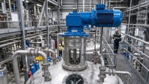
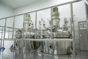
The design and implementation of heavy-duty agitation equipment are cornerstones of modern chemical processing, wastewater treatment, and pharmaceutical manufacturing. When evaluating the structural and flow dynamics required for large-scale operations, engineers must carefully consider the spatial geometry of the containment vessel to ensure that mechanical energy is uniformly distributed throughout the batch. Among the various configurations available, vertical agitation remains the industry standard for achieving symmetrical, highly controlled flow patterns. By partnering with specialized manufacturers, facilities can deploy advanced top-entry mixers custom-engineered to overcome the unique rheological challenges of their fluid processes. Through meticulous fluid-dynamics, shaft-stability, and power-transmission calculations, these robust systems guarantee the continuous batch consistency necessary to sustain profitable industrial production.
Fundamental Principles of Vertical Agitation
Fluid Dynamics and Symmetrical Flow Patterns
Top-entry mixers are installed on the roof or upper structural supports of a process vessel, allowing the main shaft to drop vertically into the liquid column. This centralized positioning is crucial because it promotes efficient top-to-bottom fluid turnover and ensures that the mechanical forces remain entirely symmetrical across the radial axis. When the impeller rotates, it relies on fundamental principles such as Bernoulli’s equation to convert the motor’s mechanical torque into localized kinetic energy in the fluid. Depending on the selected impeller geometry, the resulting flow pattern will generally fall into one of three distinct categories. Axial-flow impellers use angled blades to push the fluid parallel to the shaft, driving material down to the tank floor, where it sweeps outward and travels up the vessel walls in a continuous cyclic loop. Radial flow impellers eject fluid perpendicular to the shaft, slamming the liquid into the tank walls before it splits upward and downward to return to the central low-pressure zone. Tangential flow impellers, which are frequently used in highly viscous environments, generate a rotational sweep that forces the material to follow a circular path alongside the rotating blades.
Overcoming Shaft Deflection and Critical Speed Constraints
Because these vertical systems rely on a free-overhung shaft supported solely by bearings at the drive end, the metal’s structural integrity becomes a critical engineering constraint. Every rotating shaft behaves as a highly elastic structure with a natural resonant frequency determined by its length, diameter, and the mass of the attached impellers. The specific rotational velocity that excites this natural frequency is called the critical speed. No machined shaft is perfectly straight, and no impeller is flawlessly balanced, meaning microscopic static unbalances always exist within the assembly. As an agitator approaches its critical speed, these inherent physical unbalances interact with centrifugal forces to produce a violent phenomenon known as whirling, causing the shaft to bow outward similar to the swinging arc of a jump rope. If an operator forces the machinery to run at this resonant frequency, the radial deflection will amplify exponentially with every rotation, inevitably destroying the mechanical seals, shattering the gearbox bearings, or yielding the shaft material until catastrophic fracture occurs. To safely navigate this dynamic threat, engineers painstakingly design heavy-duty agitation systems to operate at a maximum of sixty-five to seventy percent of their first critical speed, ensuring the equipment remains permanently isolated from the theoretical danger zone.
Precision Component Engineering for Top-Entry Systems
Impeller Geometry and Power Number Correlations
The primary interface between the mechanical drive and the chemical process is the impeller, and its geometric profile determines the total energy drawn from the electric motor. The power consumed by a rotating impeller in a turbulent fluid medium is determined by a highly non-linear relationship governed by the fluid density, the cube of the rotational speed, and the fifth power of the impeller diameter. Because the diameter variable carries a fifth-power exponent, even a marginal increase in the blade span demands a staggering increase in horsepower. Doubling the diameter of an impeller while keeping the rotational velocity constant multiplies the power requirement by a factor of thirty-two, demonstrating why precise fluid sizing is absolutely essential during equipment scale-up. Engineers use a dimensionless number, the power number, to characterize the drag coefficient of different impeller types. A standard pitched-blade turbine typically exhibits a relatively low power number, whereas a heavily bladed Rushton disk turbine designed for gas dispersion has a significantly higher power number of approximately 5.5. When upgrading pilot plants to full-scale commercial facilities, engineers strive to maintain a constant power per unit volume, guaranteeing that the larger batch experiences the exact same mixing intensity and shear rates as the laboratory formulation.
Advanced Baffle Design to Prevent Solid-Body Rotation
An impeccably designed impeller will still fail to produce a homogeneous mixture if the process tank is structurally deficient. When a powerful impeller rotates inside a smooth, unbaffled cylindrical tank, the fluid eventually synchronizes with the shaft’s rotational velocity, resulting in a highly inefficient state known as solid-body rotation. This chaotic swirling motion creates massive central vortices, invites excessive air entrainment, and completely eliminates the turbulence required for molecular blending, ultimately allowing heavy particulate matter to accumulate in stagnant dead zones on the tank floor. Engineers resolve this hydraulic failure by welding flat metallic plates, known as baffles, vertically along the interior walls of the containment vessel. These physical obstructions violently disrupt the fluid’s tangential swirl, forcing the rotational kinetic energy to convert into the preferred axial and radial flow streams necessary for true agitation. Standard engineering guidelines generally recommend installing four equally spaced vertical baffles, each sized at one-twelfth of the tank diameter, to achieve optimal disruption. Specialized applications may require alternative configurations, such as bottom baffles for dished tank heads to keep heavy solids suspended, or highly polished removable baffles that accommodate aggressive clean-in-place sanitation procedures without harboring dangerous bacteria.
Mechanical Drive Systems and Gearbox Service Factors
Calculating Torque and Transmission Efficiency
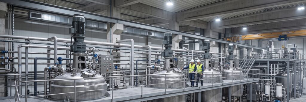
Generating the immense rotational torque needed to drive massive impellers through highly dense, viscous chemical slurries demands industrial-grade power-transmission engineering. Manufacturers outfitting facilities with heavy-duty top-entry mixers frequently rely on premium gear reducers designed to handle extreme radial and axial loads. These highly engineered drive mechanisms take the high-speed, low-torque output of an industrial electric motor and convert it into the low-speed, high-torque force necessary for heavy fluid manipulation. Agitation Resources equips its premium mixing series with robust in-line or helical gearboxes that deliver transmission efficiencies of 95% to 98%, virtually eliminating wasted electrical energy. These sophisticated drive architectures are structurally designed to support high motor outputs, up to 200 horsepower, enabling them to confidently agitate millions of gallons of dense petrochemicals or thick biological sludge without stalling. Furthermore, these gear assemblies seamlessly integrate with universally recognized electrical compliance standards, accommodating both National Electrical Manufacturers Association and International Electrotechnical Commission motor specifications to ensure global operational compatibility.
Structural Mounting and Load Distribution
Because industrial processes operate continuously under harsh conditions, the longevity of a mechanical drive system relies heavily on the rigorous application of safety margins, known as service factors. Defined by the American Gear Manufacturers Association, a service factor is a numerical multiplier that indicates the amount of mechanical overload a gearbox can safely withstand without causing permanent internal damage to its gearing or bearings. If an engineer specifies a gearbox with a service factor of exactly 1.0, the equipment has zero tolerance for sudden torque spikes and is strictly limited to perfectly uniform, steady-state operation. Real-world manufacturing environments, however, subject machinery to brutal load reversals, frequent start-and-stop cycles, non-uniform fluid densities, and severe shock loads from the addition of solid material. To protect the mechanical integrity of the drive unit, engineers strategically over-design the system by selecting a service factor of 1.5 or 2.0, which drastically increases the physical capacity of the internal components. Implementing this vital protective buffer successfully extends the operational lifespan of the internal roller bearings to well over 100,000 continuous service hours, saving the facility from catastrophic drivetrain failures and agonizingly expensive production downtime.
Specialized Applications and Process Integration
Computational Fluid Dynamics and Predictive Modeling
Historically, the design and configuration of heavy-duty agitation equipment relied heavily on expensive physical trial-and-error testing inside pilot-scale vessels. Today, elite mechanical engineers bypass these archaic methods by using advanced computational fluid dynamics software to simulate precise physical behavior in a highly detailed digital environment. By running complex algorithms that solve turbulent kinetic energy models and Navier-Stokes equations, engineers can visually map out precise velocity contours, turbulent shear zones, and pressure gradients long before any steel is fabricated. These predictive mathematical models are completely indispensable when integrating custom industrial mixers into exceptionally complex geometric tanks or biologically sensitive processes. High-performance computational modeling allows engineering teams to identify dangerous stagnation zones where reactive chemicals might pool uncontrollably or pinpoint areas of excessive fluid shear that could instantly rupture fragile mammalian cell cultures. By leveraging these sophisticated digital diagnostics, manufacturers ensure that the physical equipment performs flawlessly upon installation, eliminating the need for expensive post-commissioning retrofits.
Meeting Stringent Sanitary and Bioprocessing Standards
When vertical agitation equipment is deployed within the food, dairy, and pharmaceutical sectors, the physical geometry of the flow pattern becomes secondary to the microscopic topography of the wetted stainless steel. Standard industrial machinery usually features a basic mechanical polish that leaves behind microscopic peaks, valleys, and jagged crevices where dangerous bacterial colonies can easily attach and proliferate. To prevent disastrous biological contamination, hygienic equipment must strictly adhere to specialized regulatory frameworks such as the three-A sanitary standards or the immensely demanding American Society of Mechanical Engineers bioprocessing equipment guidelines. Typical three-A-certified machinery designed for dairy and beverage processing relies on high-grade austenitic stainless steel finished to a mechanical surface roughness average of 32 microinches, which provides excellent cleanability for moderate-risk products.
However, high-purity pharmaceutical operations producing sterile injectable medicines mandate absolute perfection, strictly requiring the use of highly pure 316L stainless steel accompanied by certified material test reports tracking the exact sulfur content for orbital welding. Bioprocessing standards require manufacturers to eliminate all stagnant dead legs from the vessel architecture and to subject the wetted components to advanced electropolishing techniques. Electropolishing is a highly aggressive electrochemical procedure that systematically dissolves microscopic surface imperfections and aggressively purges embedded free iron contaminants from the metal matrix. This elite finishing process reduces the surface roughness down to an incredibly smooth fifteen microinches while leaving behind a pristine, chromium-enriched passive layer that exhibits unmatched corrosion resistance. Securing this level of flawless sanitation ensures that the final mechanical assembly will safely process life-saving pharmaceuticals without introducing any microscopic variables into the chemical matrix.