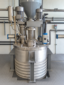
Selecting a mixer for a pressurized tank involves more than choosing a motor, shaft, and impeller. The mixer has to perform the required process duty while also working within the mechanical limits of the vessel, seal, mounting arrangement, and drive system.
That means mixer selection should start with the process.
What information is needed to size a pressurized tank mixer?
At a minimum, the following information should be reviewed:
- Tank diameter and height
- Minimum and maximum working volume
- Specific gravity
- Viscosity and expected viscosity range
- Operating pressure
- Operating temperature
- Materials of construction
- Mixing objective
- Solids loading, if applicable
- Gas addition, if applicable
- Available mounting arrangement
- Required electrical classification
- Existing nozzle and flange information
The mixing objective is especially important. Blending two liquids, suspending solids, dispersing gas, transferring heat, and maintaining uniformity at low liquid levels can require very different mixer designs even when the tanks themselves are similar.
How does the process affect impeller selection?
Impeller selection depends heavily on viscosity and the desired flow pattern.
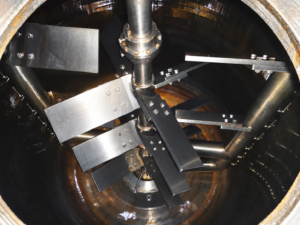
Axial flow impellers, including pitched blade turbines and many hydrofoil designs, move a large amount of fluid primarily parallel to the mixer shaft. They are commonly used for blending and solids suspension.
Radial flow impellers, such as a Rushton turbine or flat blade turbine, push fluid outward toward the vessel wall. These designs are often used when higher shear or gas dispersion is required.
There is no single impeller that is best for every pressurized tank. The correct geometry depends on what needs to happen inside the vessel.
For lower viscosity fluids, the Reynolds number is commonly used to help determine whether the system is operating in a laminar, transitional, or turbulent flow regime.
For a Newtonian fluid:
Re = ρND² / μ
where:
- ρ = fluid density
- N = rotational speed
- D = impeller diameter
- μ = dynamic viscosity
This flow regime affects both impeller performance and power draw.
How are horsepower and torque determined?
Impeller diameter and speed have a major effect on required power.
In turbulent applications, power can be estimated using:
P = Np × ρ × N³ × D⁵
where Np is the power number for the particular impeller.
The important takeaway is how strongly diameter and speed affect the result. Power varies with the fifth power of impeller diameter and the third power of rotational speed.
A relatively small change in either one can create a significant change in horsepower and torque.
That is one reason simply replacing an existing impeller with a larger one is not always a simple modification. The shaft, gearbox, bearings, motor, seal, and tank mounting all need to be considered.
Why does shaft design matter more in a pressurized vessel?
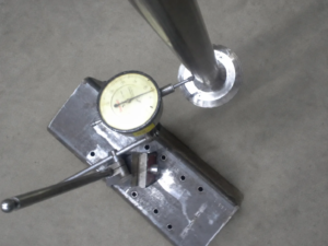
A mixer shaft has to transmit torque while also resisting bending caused by the hydraulic forces generated by the impellers.
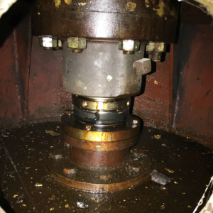
With a sealed pressurized mixer, shaft movement also affects the mechanical seal.
Excessive runout or deflection near the seal can shorten seal life and, in more severe cases, compromise containment.
Shaft design should therefore consider:
- Mixer torque
- Hydraulic bending loads
- Shaft length
- Impeller locations
- Shaft material
- Bearing arrangement
- Critical speed
- Seal requirements
- Startup and upset conditions
Long shafts may also require additional consideration for shaft stiffness, split shaft construction, intermediate couplings, or a steady bearing.
Seal selection is closely tied to this. Understanding mechanical seals in pressurized mixers covers that side in more detail.
What about the tank nozzle and mounting flange?
The tank connection is part of the mixer system.
A flange may provide the physical connection between the mixer and vessel, but the nozzle also has to support the static and dynamic loads generated by the mixer.
The vessel fabricator or responsible vessel engineer should understand the mixer loads being applied to the nozzle.
Depending on the application, these can include:
- Mixer weight
- Torque
- Axial thrust
- Radial forces
- Bending moment
Pressurized mixer applications commonly use standard flanged connections, with the exact pressure class and configuration determined by the vessel design and operating conditions.
The mixer and tank should be evaluated as a system rather than as two unrelated pieces of equipment. Safety considerations for pressurized tank agitators goes further into vessel loading and code responsibility.
The practical takeaway
A pressurized mixer should be sized around the actual process first and then checked mechanically against the vessel, shaft, seal, bearings, gearbox, and mounting arrangement.
The best starting point is usually good process data.
Tank dimensions, working levels, viscosity, specific gravity, pressure, temperature, and the actual purpose of the mixer provide much more useful information than horsepower alone.
Working with Agitation Resources
We design and build mixers for closed and pressurized vessels, on tanks up to 10,000 gallons. The mixing duty, shaft design, seal arrangement, and mounting are worked together using our own in house design software and FEA.
Send us your process data and vessel drawing and we will size the unit around the actual duty. More on our pressurized tank mixers.