
Industrial mixing requires a precise understanding of fluid dynamics and mechanical design to achieve desired process outcomes. Selecting the appropriate industrial mixing systems involves analyzing the physical properties of the materials, the geometry of the vessel, and the specific process objectives required by the facility. Engineers must evaluate variables such as specific gravity, viscosity, and the required shear rate to determine the correct motor size and gear reduction for the application. Facilities rely on equipment providers like Agitation Resources to manufacture systems that accommodate these variables through tailored mechanical design rather than generic off-the-shelf equipment. Treating the mixer and the vessel as an integrated system allows facility operators to calculate the exact power requirements needed to optimize their daily operations. Proper engineering ensures predictable performance across chemical processing, water treatment, and food production applications where process failures are costly. By establishing a strong foundational understanding of mixing mechanics, engineers can seamlessly integrate specialized equipment into their broader manufacturing infrastructure.
Analyzing Fluid Dynamics and Material Properties
The initial phase of engineering industrial mixing systems requires a thorough analysis of the fluid dynamics present within the mixing vessel. Engineers must categorize the fluid behavior into turbulent, transitional, or laminar flow regimes based on the calculated Reynolds number for the specific batch. Turbulent flow is characterized by chaotic fluid motion that promotes rapid blending, while laminar flow involves fluid moving in smooth, parallel layers with minimal lateral mixing. This categorization directly dictates the type of agitation required to achieve homogeneity within an acceptable timeframe. Operating within the wrong flow regime due to incorrect equipment specification results in wasted energy and prolonged batch cycles. Accurately defining the physical properties of the materials being combined is the only reliable method for predicting how the fluid will behave once agitation commences.
The Impact of Specific Gravity and Viscosity
Specific gravity and viscosity are the two most critical material properties that dictate the mechanical requirements of industrial mixing systems. Specific gravity refers to the density of the process fluid compared to the density of water, and it directly influences the horsepower required to rotate an impeller through the batch. A fluid with a high specific gravity requires a proportionally larger electric motor to prevent stalling and overheating during continuous operation. Viscosity measures a fluid’s resistance to flow and deformation, dictating the sheer physical force required to generate movement within the tank. As viscosity increases, the internal friction of the fluid dampens the momentum generated by the impeller, requiring specialized blade designs to maintain adequate turnover. Engineers must calculate the maximum potential viscosity during a process, particularly in chemical reactions where the fluid thickens over time, to ensure the gearbox and motor are sized for the peak mechanical load.
Evaluating Equipment Configurations and Flow Patterns
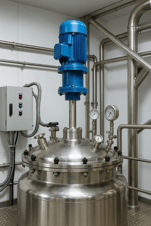
Once the fluid properties are defined, engineers must select the physical configuration of the equipment to generate the necessary flow patterns inside the vessel. The primary equipment categories utilized in process engineering include top-entry mixers, side-entry mixers, portable units, and static mixers. Top-entry configurations are standard for generating top-to-bottom fluid turnover, while side-entry configurations are frequently specified for massive storage tanks where top-mounting is structurally impossible. The placement of the mixer determines how the mechanical energy is distributed throughout the fluid volume. Generating a homogeneous mixture relies entirely on selecting the correct impeller type to translate the rotational energy of the shaft into directional fluid movement. Equipment manufacturers engineer these combinations to eliminate stagnant zones and guarantee that all material passes through the active mixing zone repeatedly.
Defining Axial and Radial Flow Requirements
Impeller selection is determined by the necessity to generate either axial or radial flow within the mixing vessel. Axial flow impellers, such as marine-style propellers or pitched blade turbines, direct the fluid stream parallel to the rotating shaft to push material toward the bottom of the tank. This downward flow hits the tank floor and travels up the vessel walls, making axial flow the standard requirement for solid suspension and rapid liquid blending. Radial flow impellers, such as flat blade turbines, discharge the fluid outward toward the vessel walls perpendicular to the rotating shaft. The fluid then splits into an upward and downward stream upon impacting the tank wall, which provides the high shear environment necessary for gas dispersion and liquid-liquid emulsification. Engineers must calculate the pumping capacity and shear profile of these specific flow patterns to match the exact requirements of the process chemistry.